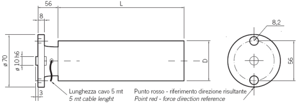
Flange mounted load cells "EPR" series are partucularly recommedended for:
-Mounting with sensor rolls having throungh shaft ends
-Mounting both inside and outside machine frame
-Installation in narrow spaces.
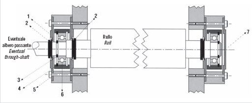
MONTAGGIO CELLE IN ESTERNO SPALLE MACCHINA
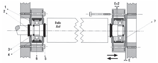
MONTAGGIO CELLE IN INTERNO SPALLE MACCHINA
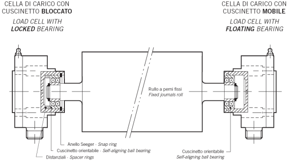
1 - Coperchio passante
2 - Tenuta V-RING
3 - Anello SEEGER
4 - Anello SEEGER per foro
5 - Vite di fi ssaggio
6 - Cuscinetto
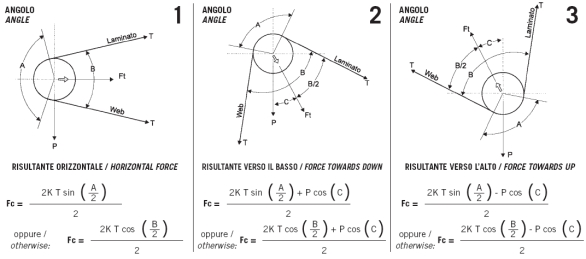
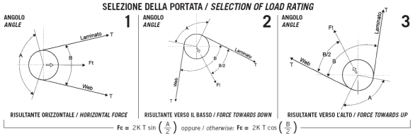
B = Angolo tra entrata e uscita laminato
Angle between entering and
exiting web
C = Angolo tra forza risultante Ft ed
asse verticale / Angle between tension force Ft and vertical axis
Ft = Forza risultante (daN)
Force due to tension (daN)
T = Tiro massimo (daN)
Maximum tension (daN)
A = Angolo di avvolgimento rullo
Wrape angle
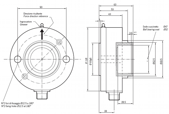
→= Riferimento direzione risultante
Force direction reference
P = Peso rullo (daN)
Roll weight (daN)
Fc = Max forma di lavoro sulla cella (daN)
Maximum force on cell (daN)
IMPORTANT: K is a transient overload factor. K is normally between
1.5 and 2.
REMARK: We reccomends to apply the load cell as per angle shown
in scheme 1 or 2. If possible avoid the use of scheme 3
Flange mounted load cells "ITR" series maintain the typical characteristics of the "ECR" series with the possibility to have higher load capacities and bigger ball bearing seats.
B = Angolo tra entrata e uscita laminato
Angle between entering and
exiting web
C = Angolo tra forza risultante Ft ed
asse verticale / Angle between tension force Ft and vertical axis
Ft = Forza risultante (daN)
Force due to tension (daN)
T = Tiro massimo (daN)
Maximum tension (daN)
A = Angolo di avvolgimento rullo
Wrape angle
→= Riferimento direzione risultante
Force direction reference
P = Peso rullo (daN)
Roll weight (daN)
Fc = Max forma di lavoro sulla cella (daN)
Maximum force on cell (daN)
IMPORTANT: K is a transient overload factor. K is normally between
1.5 and 2.
REMARK: We reccomends to apply the load cell as per angle shown
in scheme 1 or 2. If possible avoid the use of scheme 3
IMPORTANT: K is a transient overload factor. K is normally between
1.5 and 2.
REMARK: We reccomends to apply the load cell as per angle shown
in scheme 1 or 2. If possible avoid the use of scheme 3
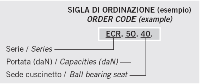
Flange mounted load cells "ECR" series are suitable for assembling on a roll sensor end part (extremity).
The standard application provides the fixing on a machine frame or base fixing by means of a "L" profile.
The constructive accuracy and the high metrological performance are able to ensure an extremely precise output signal.
B = Angolo tra entrata e uscita laminato
Angle between entering and
exiting web
C = Angolo tra forza risultante Ft ed
asse verticale / Angle between tension force Ft and vertical axis
Ft = Forza risultante (daN)
Force due to tension (daN)
T = Tiro massimo (daN)
Maximum tension (daN)
A = Angolo di avvolgimento rullo
Wrape angle
→= Riferimento direzione risultante
Force direction reference
P = Peso rullo (daN)
Roll weight (daN)
Fc = Max forma di lavoro sulla cella (daN)
Maximum force on cell (daN)
IMPORTANT: K is a transient overload factor. K is normally between
1.5 and 2.
REMARK: We reccomends to apply the load cell as per angle shown
in scheme 1 or 2. If possible avoid the use of scheme 3
RED-Renato Desirò Via Sant'Anna,51 20015 Parabiago (MI) Italy Tel +39 0331 491452 Fax +39 0331 493591 e-mail: info@red-products.it